
The CLIC drive beam linear accelerator (DBA) relies on the generation of a 1 GHz RF power [1]. The RF power production efficiency is one of the major concerns in the CLIC DBA, in particular for reaching c.m.s energies of 1.5 and 3 TeV and remains a critical parameter for the implementation of CLIC. At 3 TeV the RF power is responsible for around 50% of the entire accelerator complex power consumption. In the current CLIC DBA configuration, each accelerating structure is powered by an individual klystron capable of delivering 20MW, 150 microsecond RF pulses at a 50 Hz repetition rate. Such klystrons based on the Multi-Beam Klystron (MBK) technology have been developed and tested in industry providing a 70% RF power production efficiency. More recently, new klystron bunching technologies have been developed. It has been reported that RF power production efficiency can be increased up to 80% and above. Such an increase in the efficiency of the CLIC RF power sources could have an important impact on the overall machine power consumption. However, the direct use of such technologies for the CLIC type MBK klystron meets serious technical challenges that makes their application almost impractical.
The original idea to use a DC post acceleration (PA) of the pre-bunched beam in the single beam klystron was proposed in 1963 [2]. Experimental studies of this proposal were done a few years later [3]. In these experiments, the positive biased voltage was applied to the gap of the penultimate RF cavity, resulting in the beam perveance reduction prior to the output cavity. As an outcome, the klystron efficiency was increased from 45% to 60% without modifying the length. Recently, as an attempt to develop a technological and compact solution for high efficiency, high power L-band klystrons, these ideas were revisited and further improved in application to the CLIC MBK [4]. In its novel configuration with Two Stages (TS) MBK, the cathode and the two stages are connected in series (see Fig. 1). The high-voltage PA gap is located in the middle of the designated drift tube and separates the two stages, so that the second stage and the collector are connected to the ground potential. The first stage operates at a relatively low voltage (high perveance), thus the bunching circuit length can be rather short. The second stage deals with a high voltage (low perveance) beam. The TS configuration combines the high RF power production efficiency with a very compact RF circuit length. In addition, the second stage can be operated in DC mode, thus the modulator topology can be simplified (cost).
![Fig. 1: Tentative layout of the CLIC TS MBK (not to scale) [4].](/sites/default/files/inline-images/Figure%201_Klystron_reupload.JPG)
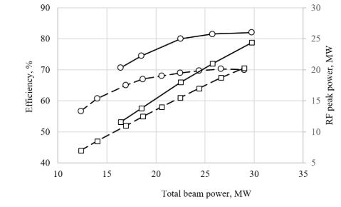
A detailed design of the CLIC TS MBK (30 beams) has been made at CERN, see Fig.1. The tube comprises 6 RF cavities with RF circuit length two times shorter than in the commercial counterpart. The main TS specific issue, RF power radiation into the PA gap, was mitigated by implementing a special resonant rejector RF circuit. The full tube simulation using the sophisticated 3D Particle-In-Cell computer code confirmed that 82% RF production efficiency can be reached. That corresponds to the 24MW peak RF power. The additional 4MW RF power (compared to the existing MBK, see Fig.2) will reduce proportionally the overall number of klystrons in the DBA and the length of the DBA itself.
The TS MBK technology can potentially also be beneficial for the CW UHF Megawatt level devices that are expected to be used in future large-scale accelerators such as the Future Circular Collider. With such power levels, the tube can operate at the relatively low HV (V1+V2<60kV), thus the use of the oil insulation will not be mandatory. The number of beamlets can be reduced and the cavities topology can be simplified. It also will be possible to implement a 2nd harmonic cavity in the RF circuit and to reduce the circuit length by an additional 30%. A preliminary study of the 0.8 GHz, 1.4 MW TS MBK for the FCC, operated at 60 kV with RF power production efficiency above 80%, showed that a very compact (0.6 m) length of the RF circuit is feasible.
References:
- A Multi-TeV linear collider based on CLIC technology: CLIC Conceptual Design Report, edited by M. Aicheler, P. Burrows, M. Draper, T. Garvey, P. Lebrun, K. Peach, N. Phinney, H. Schmickler, D. Schulte and N. Toge, CERN-2012-007
- I. Hefni, “Variable-drift biased-gap klystron,” in High Power Tube Program, MIT Lincoln Lab., Lexington, Mass., pp. 7-13, June 1963.
- J. Walder and P. R. McIsaac, ‘Experimental Analysis of Biased Gap Klystron’, IEEE Transection on Electron Devices, Vol. ED-13,No. 12, December 1966
- J. Cai, I. Syratchev, ‘Modeling and Technical Design Study of Two-Stage Multibeam Klystron for CLIC’, IEEE Transactions on Electron Devices ( Early Access ), published 12.06.2020. Link: https://ieeexplore.ieee.org/document/9115885